
Design Delivery Models: Phasing and Why FEL Doesn’t Work for New Technology
Historically, megaprojects have been managed with rigid stage-gating, formal project governance, and sophisticated project controls methodologies, especially those projects with high risk of overrun or with tight profit margins. However, as the computing world has continued meeting Murphy’s Law and hardware improvement cycles have become ever shorter, the AEC (architecture, engineering, and construction) industry has evolved new project delivery models to enable faster capital infrastructure delivery and flexible “inputs,” or design bases. The general AEC strategy involves phased project delivery or “progressive design,” allowing parts of the project to proceed when the design basis is locked while waiting for later design inputs for later phases. The transition to a phased delivery model can be stressful for project teams–especially executives–used to fully defining a project and making a Final Investment Decision before proceeding to execution. It seems like there wouldn’t be any way to control ambiguity and change on the project, leading to higher risk and higher overall cost. However, delays in time to market also come with enormous opportunity cost, and in many cases, the best course of action is to lock a design basis for a phase of the project that protects for the amount of ambiguity present in the design at the time and proceed forward. This approach also involves phased project controls and phased stage gates or other governance frameworks, to balance change control with speed and flexibility.
This field guide also presumes the use of the only correct project management methodology, the waterfall approach or hybrid-waterfall (some amount of task-based project management within a phased waterfall structure). Agile project management has no place in hardtech (even in R&D!) or capital projects and is a recipe for unbounded chaos.
BIM LOD’s and Why They Matter
Before getting into the finer details of each delivery model, we need to understand the basics of Building Information Management (BIM) Levels of Detail or Levels of Development (LOD’s). United BIM and Autodesk have some good explainers. Generally speaking, the higher the LOD, the higher-fidelity the 3D model. When modeling a pump, for example, LOD 100 might be just a 3D box, LOD 200 might be a few cylinders of different sizes on a rectangular pump base, LOD 300 actually looks like a pump but has simplified geometry, LOD 400 is the actual fabrication-level detail the original equipment manufacturer (OEM) would use to fabricate the pump, and LOD 500 is the as-built condition, either provided by the OEM post fabrication or 3D scanned using LIDAR or some other reality capture technology and imported to the model. The federated model used for design may still simplify the geometry of an LOD 400 model, as in, if a SolidWorks file or .stp file is provided, this may be simplified to a Revit family to avoid slowing down the Revit model with fine-mesh geometry, but the external dimensions maintain the accuracy of the higher LOD. This concept of accuracy applies to all disciplines. Each project should (but doesn’t always) get a BIM Execution Plan that defines the LOD to which each discipline will design. Some disciplines may only model to LOD 200; others still may only be required to provide 2D schematics or one-lines and it’s left to the contractor to provide a 3D model or field route. The latter approach is incorrect and is a recipe for disaster, but it happens, especially on smaller commercial builds.
The OG Delivery Model: Front-End Loading (FEL) / Front-End Engineering and Design (FEED)
To understand the current tension in design delivery, one must first master the traditional industrial benchmark: Front-End Loading (FEL), often used interchangeably with Front-End Engineering and Design (FEED). FEL was developed by and for the process industries—oil, gas, and chemicals—where the entire project is defined by the process equipment and everything else (buildings, structures, electrical, controls) is secondary. Oil and gas and petrochem are also huge-volume, low-margin businesses, especially in more commodity chemicals, where profit margins are cents on the pound or on the MMBTU. Profit is realized by reliably predicting the CapEx and OpEx over the next 30-100+ years. Inherently, the FEL process seeks to minimize risk and spend. Additionally, risk evaluation tools such as PHA’s, LOPA’s, and HAZOP’s place large costs on catastrophic impacts (as they should), and uptime is paramount. Reliability and redundancy is therefore highly valuable and baked in via many industry best practices. The FEL/FEED model is therefore characterized by a linear, stage-gate progression designed to minimize capital risk by locking in the process definition before committing significant expenditure. Canceling a project in design is always cheaper than the sunk cost of a failed project.
FEL/FEED has four to five primary stage gates:
FEL-0: Initial Concept
FEL-1: Define
FEL-2: Assess
FEL-3: Select
FEL-4: Detailed Design & Execution
This delivery model should be farcical on its face based on the above to any seasoned PM–imagine developing the FEL process from scratch today and grouping the entirety of project execution and >90% of the project spend into a single phase–and yet it persists.
The journey through FEED begins at FEL-1, the Conceptual Design phase, where the primary objective is to Define what the process is trying to do, evaluate alternatives and quantify high-level risks. At this stage, the project is a collection of Block Flow Diagrams and preliminary equipment lists, supported by a Class 5 cost estimate that carries a +50% to -30% variance. As the project matures into FEL-2, or Preliminary Engineering, the focus shifts to Assessing the best identified project approaches and quantifying the economics through Process Flow Diagrams (PFDs) and material balances. By the time a project reaches the conclusion of FEL-3 (Basic Engineering), the technology is Selected and the project is considered "bankable". This is the Final Investment Decision (FID) gate, where the scope and execution plan are finalized, and capital is appropriated. At FEL-3 the contingency is assessed at +20% to -15%.
The inherent logic of FEL is "measure twice, cut once." It assumes that by the time you exit FEL-3, you have a definitive understanding of your project costs. This is the first pitfall for projects other than oil, gas, and petrochem: at this point of the project, the big players and even many of the small players do indeed know their project costs to this level of accuracy. Capital costs in these industries are so widely studied and so highly valuable that new price indices and inflation factors are published every year, even for specific pieces of equipment. For anyone else not using these indices or without several decades of internal project cost data, pricing the project to this level of accuracy at FEL-3 is impossible. Why? Two reasons. First, FEL/FEED treats any building and its ancillary systems as secondary to the process. For hardtech, manufacturing, data centers, etc. the building is a crucial part of the project–housing sensitive equipment, providing process cooling, providing conditioned, filtered, dehumidified air, etc. Except for the most complex equipment, the building and associated infrastructure, site work, etc. will average around 50% of the total project cost. Second, at FEL-3, only the process and piping is usually modeled in 3D. Other major infrastructure such as substations, motor control centers, and duct banks could be modeled, but in most cases, all other disciplines only deliver 2D schematics as inputs to the “final investment decision.” Instrumentation and control panels likely aren’t shown at all. Because of the vast amount of project cost data available for oil, gas, and petrochem projects, this is fine for them to price. For everyone else, this is impossible to estimate. A +/- 15% estimate is only possible on a design modeled at least to LOD 300 with material take-offs or bills of material at the same level of detail.
Put a different way, the conundrum within FEL/FEED is that the process itself is not fully defined until FEL-3, so other disciplines by definition cannot be fully defined until some point after FEL-3. Take an indoor process, for example a baking process. If the quantity and type of ovens are not defined until FEL-3, then the electrical load, the heat to space, the cooling requirements, the space occupancy, etc. are also not defined until FEL-3. Electrical, mechanical, architectural, structural, and controls can’t begin their FEL-3-level design until the process FEL-3-level design is defined. This is all punted to “detailed design” with no other phases or stage gates. Deciding between models of motor starters with a $30K differential per unit? Execution phase. Deciding whether to use rebar or fiber for slab reinforcement and whether that affects concrete thickness? Execution phase. If you’ve hired a large EPC, they might price all this at FEL-3, but they’ll pull the API guide that says any motor > 5000 hp needs concrete 3 feet thick when an equipment-specific design could have saved half that. There is no time or space saved in FEL/FEED for value engineering for the rest of the disciplines. It’s an entirely outdated model that only works well for the specific projects it’s built for.
The AEC Paradigm: Phased Delivery
In response to the failures of FEL in high-stakes environments, many advanced manufacturing sectors have adopted the AEC (Architecture, Engineering, and Construction) delivery model, sometimes just called “Architectural Design,” common in semiconductor fab design. Unlike the linear process-first approach of FEL, the AEC model treats the facility as a holistic system from day one, where the building design is dependent upon what’s going in the building, and the process design is at least somewhat influenced by the limitations of the building, if any (available land, maximum clear height, zoning and building code requirements, etc.). From there, the design and execution is broken into phases based on what is needed to be built first and what information can be reasonably known or locked in by the deadlines required to meet the construction timeline.
Herein lies the other advantage of the AEC approach vs. FEL: in advanced manufacturing, process equipment lead times are often much shorter than process equipment lead times for large-scale oil and gas projects. Many steps of assembling a widget are mechanical assembly or conveyance, where the manufacturing challenge is primarily dimensional accuracy and not management of extremely hazardous or corrosive chemistry with exotic, long-lead alloys or specialty lined piping or vessels. Sub-components are readily available, or even whole production lines, given the extremely fast design and manufacturing iteration timelines China has managed to implement and perfect. When the process equipment is readily or imminently available, and when the equipment needs to be placed into a building, usually with some amount of cleanliness requirement before equipment move-in, the left-to-right schedule then isn’t driven by the equipment availability but by the building availability. This is especially true on a greenfield project: in order to land equipment that may have a 9-month or even 6-month lead time or less, the project team must select a site, identify major utility expansion requirements, extend major utilities to the site, take geotech samples of the site, develop a stormwater management plan and design for either drainage or retention ponds, permit the design, grade the site, design the building core and shell, permit the core and shell, pour the foundations, erect the steel, pour the slab, construct the walls and roof, weather protect the building, and have some level of fire suppression, emergency response, and dust/contamination control available. In order to design the core and shell, you need to have a minimum amount of information on the interior needs of the manufacturing process, such as overall process layout, utility needs, and hazardous chemical quantities, in order to ensure the building structure can accommodate the loading of the equipment and associated piping, busway, cabling, ducting, HVAC units, etc., and is designed to the appropriate building codes for the hazards involved including fire separations, fireproofing, or specialty sprinkler systems as required. The left-to-right critical path, then, is driven by building “dry-in,” or time to this minimally ready core and shell, which is then usually driven by the building steel lead time or the foundation construction timeline, including rebar design and fabrication, form construction, and cure times of concrete–exacerbated by cold temperatures and lengthened cure times in winter months.
The AEC process on an industry-wide basis optimizes for processes that are primarily indoors, first designing and constructing the building, then any utilities that are needed to be in place before process equipment installation, or “tool install,” then tool install and final connections. But the general idea of phasing a project for what’s needed first can be applied to any large project–the advantage being that even for outdoor, process-driven projects, no other discipline is left out of early consideration and the project is treated as a whole from the start. For an energy-heavy outdoor process, the initial phase would likely focus on foundations and electrical equipment optimization, comparing the costs and timelines of indoor- vs. outdoor-rated substations, various physical configurations of process equipment that affect total heights, weights, and conveyance distances, etc., rather than focusing on just choice of technology and material and energy balances for the Final Investment Decision.
AEC Design Process: 30-60-90-IFX
The design process under this delivery model still has some amount of pre-design, or “scoping,” and concept design, or schematic design, prior to detailed design. These can be developed into any level of stage-gating or executive reviews the program management team desires or finds useful, which will highly depend on the individual company, their internal processes, and what aspects of the design or total project cost/schedule that the executive team cares about. For example, on highly schedule-driven projects, scoping may involve an engineering study on major utility equipment to be purchased with extremely long lead times, and each long-lead system may require its own design review with execs prior to locking that particular concept and therefore input to the building/site design. In other companies, executives may not care about the particulars and only may require that the lead time of major equipment be shortened as much as possible, or that total cost be lowest with some sacrifice to schedule. Each project should go through some amount of executive optimization testing during scoping–this isn’t required by the process per se, but ensuring alignment on not just the absolute objectives but where the execs will place more value if they have to make a tradeoff early on in the design process can save a lot of headache and rework later.
Once the scope of the project is defined, typically a Basis of Design document is created for each discipline that sets the guiding design principles of the project. This can and should be a living document, and the format should always be chosen to match the way the particular team and company actually works. If a company heavily relies on slide decks for reviews and conveying information, for example, making the Basis of Design a large spreadsheet or word document is unlikely to be user-friendly and therefore unlikely to be updated or even referenced regularly. Some companies may not even make a document and may just agree upon a set of reference documents to follow for the design, e.g., a set of vendor P&ID’s for process equipment is considered final for design kickoff for the ancillary systems. Regardless of the method, the design starting point is defined, and Detailed Design or Design Development begins.
Some firms will then proceed to do the entire detailed design process internally (as an external party to the Owner) and submit IFR (Issued for Review) or IFA (Issued for Approval) deliverables to the Owner at the end. This is incorrect and unacceptable on both the Owner and third party’s side. Inevitably this leads to late comments and corrections to the details of the design if not to the underlying design basis, which then creates rework, more reviews, etc. The only acceptable and correct approach is to do intermediate design reviews, usually following a 30-60-90-IFX (Issued-for-X, e.g., issued for bid, issued for permit, issued for construction) system. The numbers refer to the percent completion of the design: 30% complete, 60% complete, and 90% complete. Through our vast experience on dozens of Giga-scale, extremely fast projects, we have refined our 30-60-90 approach to a one-size-fits-all set of definitions:
30% Design = 2D design complete
60% Design = 3D design substantially complete but not coordinated or pipe stressed
90% Design = 3D final design, coordinated, pipe stressed, post-HAZOP, with engineered supports if needed
IFX = design complete for the level of issuance required (for bid, for construction, for fabrication, etc.)
These are milestones for customer review, where the customer is anyone who is not a direct member of the EPC team, as in, execs, operations and maintenance teams, quality control managers for the product or process, manufacturing process engineers, construction managers, superintendents, etc. Between these milestones, the design team should be both discussing the design details regularly offline and having formal progress meetings with the design manager/design coordinator. The milestones are not coordination reviews. The design is coordinated internally to the EPC team and the milestones involve presenting the holistic design concept with the details worked out to the teams that actually have to construct, operate, and maintain the systems in order to get their feedback during the design phase rather than at the end or after the fact. At no point, ever, should construction documents be issued without having been reviewed previously with a construction team. If GC’s or subcontractors aren’t engaged until after drawings are available, this means the owner must employ or have engaged some amount of construction expertise internally. Frontloading design feedback and avoiding rework is a non-negotiable.
At these intermediate milestones, it is possible to release the documents to construction firms or other third parties (e.g., panel fabricators, material vendors) to begin pricing or procuring before the design is complete. The documents can be marked Issued for Bid or Issued for Procurement even at a 60% level, because the percent completion is always in reference to the Issued for Construction level of completion, even if the final documents are only intended to start a construction bid cycle and are only for bid. It is up to the design team to decide what level of completion is required for early procurement and define the specific deliverables and level of detail needed for an “early release.” Early releases may also only pertain to one or certain disciplines or even parts of the project–for example, if building steel lead times and steel mill roll dates are extremely critical to the schedule, the structural engineering team may prepare and issue several early releases to begin procuring and fabricating the steel prior to the rest of the core and shell being designed. In this case, just the steel set and maybe the foundations are released and locked, but the slab on grade, walls, utility supports, etc. can be detailed later.
Phased Packages: Site Civil, Core & Shell, Basebuild/Mains, and Tool Install
As described above, most megaprojects in advanced manufacturing will be driven by the building itself. Phasing the project first breaks the project into large scopes of work that are likely led by different subcontractors or even different GC’s entirely. These are typically:
Site Civil and Early Works/Site Utilities
Core and Shell or CSA (Civil, Structural, Architectural)
Mechanical, Electrical, Process/Plumbing, and Controls (MEPC) Basebuild
Tool Install, sometimes broken into 1.0, 1.5, and 2.0 phases
A note on acronyms: MEPC is usually referred to as MEP in typical commercial designs, but this acronym stands for Mechanical, Electrical, Plumbing, entirely leaving out Process and Controls. We prefer to use MEPC for several reasons: dry mechanical and hydronics/wet mechanical are usually better served by two different engineers/designers, as dry mechanical involves airflow and ducting rather than fluids and pipes. Dry mechanical and ducting is usually a separate subcontractor from piping or plumbing with different LOD requirements, and hydronic piping is trivial for a process piping team. A process piping team will also have a higher level of detail by default and a higher standard for P&ID’s. Plumbing is also trivial for a process piping team and overlaps more with civil/environmental engineering from a code and construction perspective than with mechanical engineering. Controls is also usually an afterthought in commercial construction but is critical to the design in advanced manufacturing. MEPC may seem too particular, but is more inclusive, is more indicative of a fully coordinated design, and ensures controls doesn’t get left out.
Once the major phases are defined, each major phase usually has several sub-packages. Site civil, for example, may be broken into rough grading, fine grading, parking lots and paving, below-grade utilities, and landscaping. This allows for less refined, lower detail parts of the project to be released earlier, such as rough grading to do major cut/fill work prior to geotech being available for foundation and slab design that will dictate the building extents and therefore fine grading. Parking lots and paving usually needs low voltage electrical for power poles, light pole selections, sometimes wifi or hardwired telecom for security cameras, maybe fencing–seemingly trivial, but a lot of details affecting an actually broad range of stakeholders (network, security, operations, logistics, etc.). Waiting until the parking lots are fully designed to do fine grading isn’t required and sometimes isn’t allowable in a tight schedule.
This same concept applies to the core and shell: this may be broken into foundations and steel, slab on grade, then a “shell” package with wall and roof finishes, and maybe another for finer details such as doors and openings, glazing, trims, roof-mounted air handling equipment, etc. For MEPC packages, Basebuild may include only Mains, with isolation valves/breakers/etc. at each major building block or “shop,” or at building gridlines without respect to manufacturing layout, or Basebuild could be a more detailed/more refined utility distribution design to a 1.0 Tool Install level, which is usually an isolation point within 1 building bay (one grid square) of the final tool connection. There may be separate packages entirely for a Central Utility Building or central utilities area. Interior spaces such as chemical storage rooms, maintenance areas, break rooms, etc. may be detailed in the Basebuild or Tool Install phases rather than in the Core and Shell phase. Finally, 1.5 and 2.0 Tool Install phases then bring utilities to within even closer distances, usually +/- 3m to the tool then the exact final connection. The packaging strategy is entirely driven by the schedule: when information is needed, when information is available, lead times, and construction sequences. The program manager, design manager, construction manager, and their support teams all work together to figure out what’s possible and what the best strategy is for the project at hand.
Once the packaging strategy is defined, each package goes through the 30-60-90 process. The deliverables at each intermediate milestone then also vary per package and per project.
A 30-60-90-IFC example approach for a Core and Shell package is below:
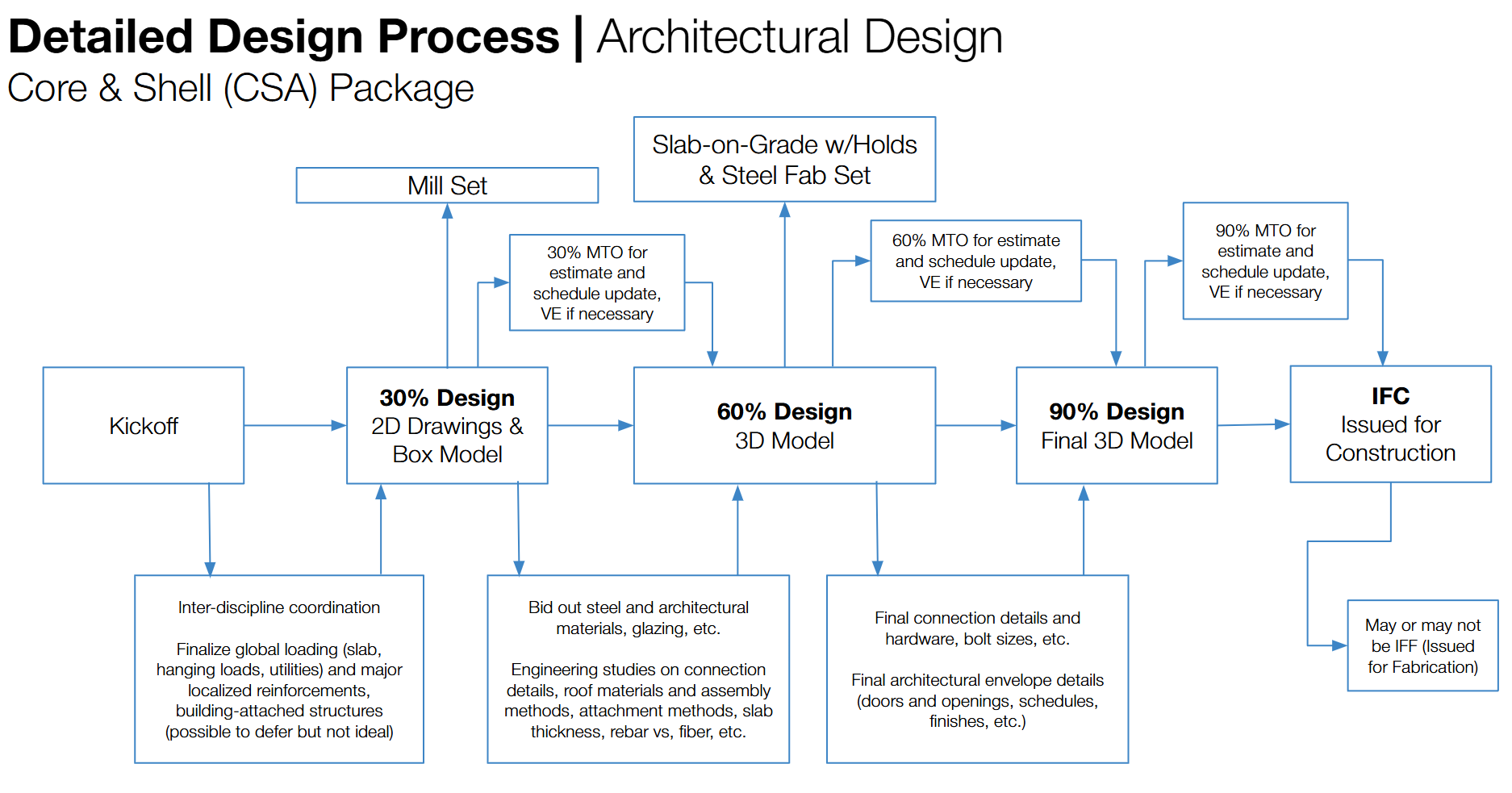
copyright Aurelia Consulting LLC
And another for a basebuild Mechanical, Electrical, Process/Plumbing, and Controls (MEPC) package:
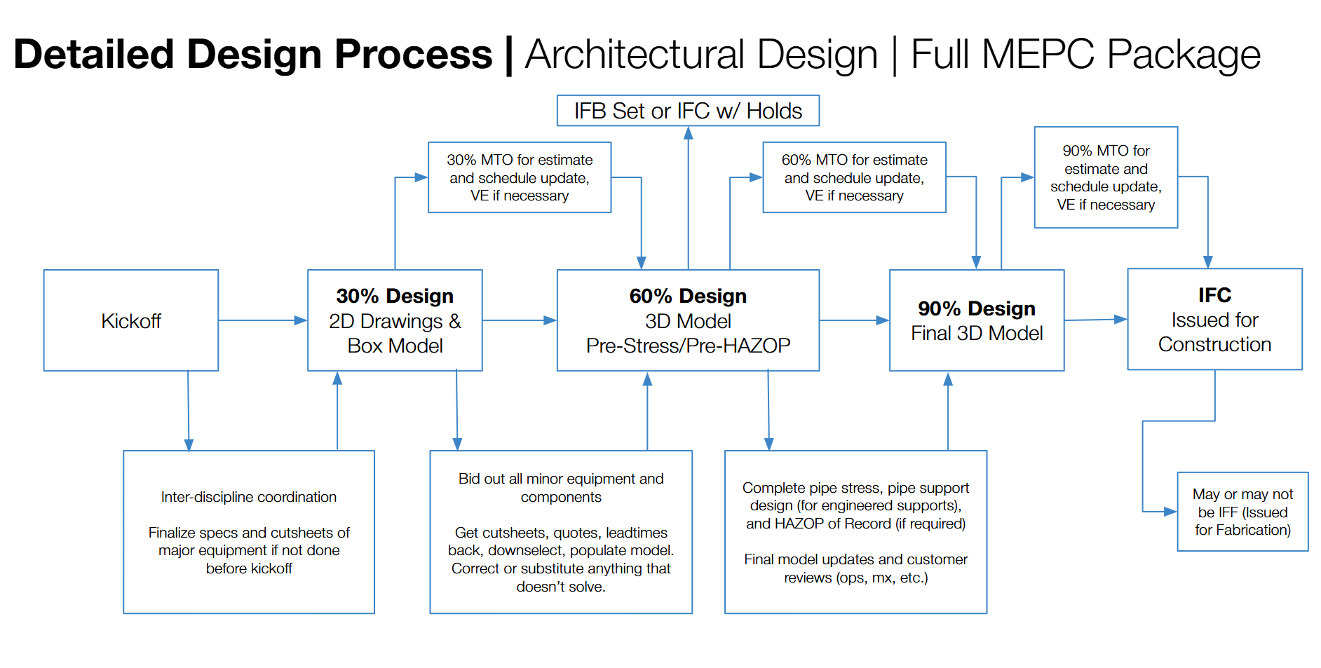
copyright Aurelia Consulting LLC
The Real Difference is Philosophical
At this point you may be thinking that the only drawback to FEL is that there isn’t any definition to detailed design during FEL-4 and that the packaging strategy can be applied there. You are correct, that is a possibility, as long as the upstream FEL stage gates are approached more holistically and involve the other disciplines. However, the real difference is in the mindset and the approach of the project team and the design disciplines. Design and project teams used to a slower pace, more rigid stage gates, and highly sequential, process-driven design logic, are going to find that the AEC approach is too chaotic and goes “out of order,” or lacks control on the design. These people may disparage the design team during the detailed design process, saying that they can’t effectively execute or control the project when the design is still evolving. This is an inherent weakness in these types of teams: phasing does not mean lack of control or that elements of the design are not locked and approved. Each large and intermediate milestone is a stage gate. Every project team member is empowered to add more checks and controls if they like by requesting reviews of design bases or ideas before proceeding. But, it does take a strong combination and balance of flexibility vs. controls when executing a phased project and a very strong attention to detail. This type of execution is not for the lazy project manager who thinks they will check their SPI and CPI once a week and ask their subs for answers on why the project fell behind. This is very much more active and creative management than passive, which is why it’s ultimately the better fit for innovative, hungry owner teams who know what they want and what they don’t.
If this still feels intimidating as an owner’s team–what if I don’t know enough? If the design team asks me what I want and I don’t know or I choose wrong, shouldn’t I have left it to the experts? The answer again is to trust yourself, and to keep asking questions until you understand the first principles. As the owner, you have a right to know what’s being designed and why! Keep asking, even if the questions feel dumb or basic. If something isn’t making sense to you, someone who has figured out a new technology to scale, it probably doesn’t make sense. It might be a good idea or rule of thumb not exactly applicable to your case. It might be overkill. It might still be worth doing! But if it’s worth doing, it’s worth understanding. And you really can do it. Read our post(s) about how to build the team that builds the team to learn more.